Installing our hf Antenna System
On this page you will find an illustrated report of how we renovated an antenna mast during 2000 and built and installed our hf antenna system in early 2001.
The Antenna Mast
 During
the second half of 2000 we spent several shack nights and a few weekends
refurbishing a mast (25 foot) that was kindly donated to the club by Donna
Vincent G7TZB when she moved home. The mast had not been used in anger over
the period and was, we found, extensively overgrown when collected from it's
old home. The mast was actually in splendid condition for a ten-year old
During
the second half of 2000 we spent several shack nights and a few weekends
refurbishing a mast (25 foot) that was kindly donated to the club by Donna
Vincent G7TZB when she moved home. The mast had not been used in anger over
the period and was, we found, extensively overgrown when collected from it's
old home. The mast was actually in splendid condition for a ten-year old 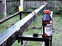 item that hadn't been touched, needing a little bit of
TLC to bring it back to something like the original condition.
item that hadn't been touched, needing a little bit of
TLC to bring it back to something like the original condition.
The first thing we did was to strip the mast apart and order a new winch and cable from Tennamast. Then members took it in turns to wire brush the rust away before we could prepare it for painting. After spending two Friday nights wire-brushing the surface rust off the mast, the time approached to prepare the surface for painting - although we haven't decided what colour it's going to be just yet.
So, out came the trusty Jenolite and three of the four sides of the mast were duly coated with the magic liquid. Of course during the course of this being done, by one member of the club, all the other members retired into the shack to partake of tea and biscuits again.
Digging the Hole
 Another
Friday evening - another day in the mines! Or that was how it felt by the time
the evening had drawn in, and it had become too dark that we could no longer
see to dig the hole for the mast base.
Another
Friday evening - another day in the mines! Or that was how it felt by the time
the evening had drawn in, and it had become too dark that we could no longer
see to dig the hole for the mast base.
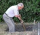
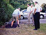
As with any mast that is to be some 25 - 30 foot high, it needs a good base, and in the case of our donated Tennamast, the recommended 'lump' of concrete' in which its base post should be set is a minimum of one cubic yard. We decided on a cubic metre!
So, the team of Dave, Colin, John, Mike (overseer), Graham (head tea-boy), 'Tex' and a variety of others, many of whom mysteriously found they had medical exemption chits, surrounded the small plot of land that was to become 'host to the post'.
At first the digging was comparatively simple and easy as
the very sandy top-soil was easily loosened by pick (Tex), shovelled into the
barrow (Dave), then wheeled away (John and Colin). 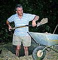
Then as the shadows lengthened (just before disappearing) tragedy struck!. We came across the real problem about half way down. The top-soil had given way to a rock-like hard packed clay. Although the pick would still go into the clay, breaking it up to lift out was another matter.
But this wasn't to be the worst part of the job. The packed clay gave way to what felt like sandstone. The stuff was, in fact, half way to becoming sandstone and the work became even harder as shifts of picking-and-shovelling became shorter.
An added problem also which none of us had considered, was climbing in and out of the hole. So, at around 9:30pm we had to call a halt in the proceeding having dug our way down most of the way. The prospect of having to go back the following Wednesday evening was terrifying. We'd all got muscles aching that we'd forgotten we should have.
When we started digging the hole for the ground-post, the weather had been warm and very dry with only midges and other flying predators to contend with. But then came the following Wednesday!
I'd like to be able to say that 'on the following Wednesday, the weather was also kind and that we finished the hole 'easily' - but I can't! The weather was abysmal. It was dark and extremely wet. Luckily the boards we had used to cover the partly dug-hole, had kept almost all the rain out - leaving only one small corner wet. The whole place had the look of a Hammer Horror film scene.
Pouring the Concrete
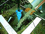 You know - wet, dripping rain, men huddled round a hole
being dug in the ground - it's at this point you know something nasty's going
to happen. But the only nasty thing that happened was that we all got very
wet. But thanks to all the hard work, the hole was dug out to the full depth
of a metre. Two days later at the Friday evening meeting the final
preparations were made to the ground-socket part of the Tennamast. This is a
short section of square-section sleeving that is fitted into the concrete
forming a 'non-scraping' tube for the base section of the mast to sit in.
You know - wet, dripping rain, men huddled round a hole
being dug in the ground - it's at this point you know something nasty's going
to happen. But the only nasty thing that happened was that we all got very
wet. But thanks to all the hard work, the hole was dug out to the full depth
of a metre. Two days later at the Friday evening meeting the final
preparations were made to the ground-socket part of the Tennamast. This is a
short section of square-section sleeving that is fitted into the concrete
forming a 'non-scraping' tube for the base section of the mast to sit in.
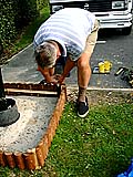
In the process of preparations Dave welded four 'legs' onto the bottom of the ground tube to allow stable positioning within the concrete 'block'.
At the unearthly hour of 7am on Saturday morning the same few people met at the hole again to await the arrival of the ready- mixed concrete man who, with a few artistic wiggles of his chute, rapidly filled the hole, with a a specially formulated concrete mix. Having poured the concrete into place in the hole, then jumped up and down on it to bed it in, we settled back to allow the concrete to harden.
 Another
good thing to come out of the work, is that with spare concrete we have
arranged a slope at the door to the shack. This has allowed us to gain full
disabled access to the shack, which we have wanted for some time. The portion
of the 'over' matter from the 'pour', used to produce a ramp to the shack was
left to harden.
Another
good thing to come out of the work, is that with spare concrete we have
arranged a slope at the door to the shack. This has allowed us to gain full
disabled access to the shack, which we have wanted for some time. The portion
of the 'over' matter from the 'pour', used to produce a ramp to the shack was
left to harden.
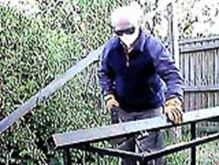
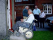
The following week Mike (shown here on his way up into the shack) tried the ramp out. His comments were 'Hmm - not bad" Praise indeed!
We were left with the 'landscaping' of the concrete to reduce the impact of its appearance, And to this end a small floral garden was suggested within a palisade.
To leave an area around the base of the mast, an old plastic bucket was pressed into service. The bucket had its bottom removed and was placed around the sleeved hole in the concrete, forming a wall, keeping the soil out.
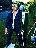
Installing the Feeders
Sunday morning the 17th December 2000 saw a major milestone achieved with the laying of the antenna feeders and the rotator control cable from the base of the antenna right back to the shack. It also coincided with first dry weekend day for weeks (months?).
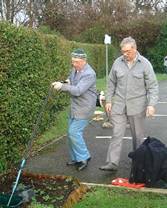
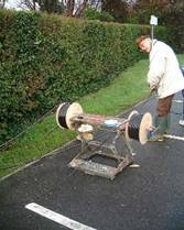
The drawstring that was put in when the ducting was laid was used to pull through a nylon rope. The nylon rope was then used to pull through 2 antenna feeders and a 7-way rotator cable, with Tex G1TEX pulling and Dave G3ZPR, Bob G0SJT and Phil G0KKL feeding the cables into the ducting. Also pulled through again was the drawstring for future maintenance purposes.
As we have a long feeder run from the operating positions in the shack to the antenna, we needed a low-loss feeder. We are using Westflex 103, chosen not only for its low loss but also its good physical properties. Our 60m run will give less than 2dB loss on all bands up to 4m, so will be ideal for our hf antenna system.
At the base of the mast the feeder, Colin G6MXL terminated the feeder in 50-ohm N-plugs. These make a virtually watertight bond to the coax.
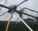
Some initial work on the fabrication of the antenna itself started in late December 2000. Dave G3ZPR started work on the centre spider for the antenna itself. The plate was cut and bored, the tubes made and welded in place at appropriate angles
Installation of the Rotator
On Sunday 14th January 2001, a working party attended at the shack with the intention of completing the new antenna system. The first arrivals made a start on the mast and winch cable assembly. Next came the fitting of the bush to the rotator cage followed by the rotator connector (multiplug) and antenna assembly.
The wire rope was attached by drilling and tapping a 8mm hole and securing with an appropriate bolt. The head was ground to shape to enable its smooth passage along the length of the outer mast. Some difficulty was experienced with relocating the inner mast but an offending bolt was ground off which allowed the inner section to locate fully inside its outer component. A replacement bolt and split pin assembly was put in place which will allow easy access on another occasion.
 The
completed mast was then lowered into position within its socket and we set
about preparing the antenna proper. Five chairs were spaced at appropriate
distances from each other to enable a temporary assembly to be made by fixing
antenna wire around the periphery and supporting with a strong, but thin,
plastic rigging cord. The whole was mounted on to the rotator cage and the
mast cantilevered up into the upright position.
The
completed mast was then lowered into position within its socket and we set
about preparing the antenna proper. Five chairs were spaced at appropriate
distances from each other to enable a temporary assembly to be made by fixing
antenna wire around the periphery and supporting with a strong, but thin,
plastic rigging cord. The whole was mounted on to the rotator cage and the
mast cantilevered up into the upright position.
A discussion ensued and it was decided to lower the mast again and connect the rotator motor in order to be able to re-orientate the antenna into the 'parked' position. We could now rotate our fibreglass poles.
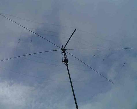
Building and Installing the Antenna
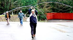
Despite the rainy start, 7 members braved the weather on Sunday 4th February 2001 to help build the VK2ABQ antenna. With the mast lowered the element-less antenna was removed and taken to an empty room where it could be worked on in the dry. After some discussions it was agreed to use hard-drawn copper wire rather than the more flexible wire originally considered.
 The
antenna was laid on the floor and the various elements measured and cut. A
The
antenna was laid on the floor and the various elements measured and cut. A 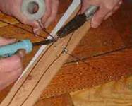 twin-wire feed system was built with the wires stapled to
a piece of wood. The elements were then soldered to the twin wire feeder. At
the end it was soldered to the down-feed coax and sealed in a plastic 35mm film
canister.
twin-wire feed system was built with the wires stapled to
a piece of wood. The elements were then soldered to the twin wire feeder. At
the end it was soldered to the down-feed coax and sealed in a plastic 35mm film
canister.
Whilst some members worked on the actual antenna, others finished off the termination of the feeders in the shack.
Shortly after lunchtime the rain stopped and Tex carried the antenna up to the mast and the bolts were tightened. The support strings to help reduce sagging in the four fibreglass rods were installed, and Dave raised the mast.
Measurements suggested that an SWR of less than 3:1 was achievable on all three bands (10m, 15m and 20m), although with some adjustments on another occasion it is hoped to be able to improve on this. Initial impressions of performance are encouraging, and one member who stayed after lunch reported that the antenna was working and bringing in good quality signals even before any adjustments.
The Antenna ready for use