Transmitter Block Diagram etc. (4a1, 4b1, 4b4 & 4b5)

Item |
Name |
Description |
1 |
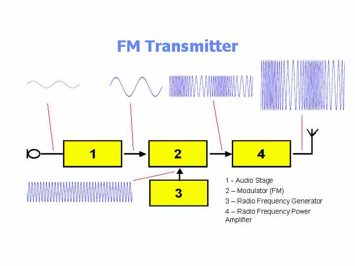
Audio Stage |
· Amplifies (increases) the weak signal coming from the microphone. |
2 |
Modulator |
· The audio (or data) signal is modulated onto the radio frequency carrier in this modulator stage. · Modulation can be by varying the amplitude (or height) of the carrier known as amplitude modulation (am) or by slightly changing its frequency waveform known as Frequency Modulation (fm). |
3 |
Frequency Generator or Oscillator |
· The Frequency generation stage (often known as the oscillator) defines the frequency on which the transmitter will operate. · Incorrect setting of this stage can easily result in operation outside of the amateur band, and hence interference to other (non-amateur) radio users. · The Foundation Licence only permits the use of commercially available equipment or commercial kits built strictly in accordance with the instructions. · The Foundation Licence does NOT permit you to design and build your own transmitters. |
4 |
RF Power Amplifier |
· The power amplification of the radio signal is carried out in the final stage of the block diagram. It makes the signal stronger so that it can be transmitted into the aerial. · The r.f. power amplifier output must be connected to a correctly matched antenna (the “Load”) to work properly. Use of the wrong antenna, or no antenna, can result in damage to the transmitter. |
You should already recognise the symbol for the microphone on the left, and the antenna or aerial on the right. If not click hear to remind yourself of circuit diagram symbols.
Amplitude Modulated (AM) Transmitter
The diagram below shows the signals at various stages through an Amplitude Modulated (AM) transmitter.

Frequency Modulated (FM) Transmitter
The diagram below shows the signals at various stages through an Frequency Modulated (FM) transmitter.