Technical Aspects
(2)
Big
and Small Numbers
Sometimes we have to deal with very large and very small numbers. We do this by using prefixes in front of the Electrical Unit. You’ll need to become familiar with these and be able to do basic calculations involving small and big numbers. You can use a calculator (scientific or normal) provided it has no programming facilities.
Factor
|
Prefix
|
Symbol
|
Notation
|
|
millionths |
micro |
µ |
x 10-6 |
|
thousandths |
milli |
m |
x 10-3 |
|
Thousands |
kilo |
k |
x 103 |
|
Millions |
Mega |
M |
x 106 |
|
Billions |
Giga |
G |
x 109 |
Examples:
6.8 kW = 6800 W = 6.8 x 10³ W
1200 mA = 1.2 A
0.5 MHz = 500 kHz = 500 x 103 Hz
10 GHz = 10000 MHz = 10 x 109 Hz
Symbols used in circuit diagrams
In order to show the design of a particular circuit on paper, we draw Circuit Diagrams. Everyone uses the same symbols, so that we can all read and understand the diagram. The symbols you need to know for the Foundation Licence are shown below
Symbol
|
Explanation
|
|
|
A cell is a small battery. It normally has a potential difference of about 1.5 Volts. Notice that it has two terminals, one has a + (positive), and the other a – (negative). |
|
|
A Battery is several cells connected together to get a higher total potential difference (or voltage). The connections are made internally so from the outside a cell and a battery can look the same.
A Battery provides voltage, but current will only flow if there is a circuit (route) for the electrons to flow out of the battery, through the various wires and components such as resistors and lamps back to the battery. |
|
|
A switch is used to safely start and stop the flow of current in a circuit. Think of a light switch at home |
|
|
A resistor constricts the rate of current flow. The higher the value of the resistor, the less the current will flow. |
|
|
A fuse will allow only a certain amount of current to flow before it breaks and stops the current flowing. It is used as a safety device.
If a circuit is designed to use under 3 Amps, then by putting a 3Amp fuse in the circuit, if a fault develops and the circuit uses a lot more than 3-Amps, then the fuse will break and stop all current flowing in the circuit. |
|
|
The use of an electrical earth is an important safety feature for many items of main-powered equipment |
|
|
A crystal is device that is used to keep an electrical circuit that is oscillating on a steady frequency. It is used a lot to keep radio circuits on one particular frequency. |
|
|
A lamp gives out light when electrical current flows through it. Think of a light bulb. |
|
|
A Light Emitting Diode produces light when direct current (DC) flows through it in the correct direction. |
|
|
An antenna (or aerial) is where a radio signal going through the air is picked up. It converts the radio signal into a current in the feeder to the receiver.
It is also used in reverse when transmitting, where it converts the signal in the wire into a signal that goes through the air. |
|
|
A loudspeaker converts electrical signals in wires into sounds we can hear. Televisions, Radios and hi-fi all have loudspeakers in them. |
|
|
A microphone converts sounds into electrical signals in wires. It is the opposite of a loudspeaker. |


Electrical
Fundamentals (2A)
Fundamental Theory (2A1)
Power (2B1)
Power is measured in Watts
Power (Watts) in a circuit is the product of the Potential Difference (Voltage) and the Current (Amps) i.e. P=V×I
Resistance (2C1)
Resistance is the property of a material that opposes the flow of electricity.
The unit of resistance is the Ohm (Ω).
Ohms Law
The current (I) flowing through a resistor is proportional to the voltage (V) across that resistor.
V = I x R
I = V / R
R = V / I
Ohms Law – Examples
12 Volts ÷ 3 Amps = 8 Ohms
24 Volts / 12 Ohms = 2 Amps
5 Ohms x 2 Amps = 10 Volts
Parallel Circuit (2C1)
In a parallel circuit the supply voltage (V) from the
battery is common to all components (the two resistors in this case). T
total current supplied by the battery is equal to the sum of currents through
each of the resistors.
Itotal = I1 + I2
The individual currents will depend on the
resistance of each item
Series Circuit (2C2)
The current (I) flowing from the battery is common to all items. The battery voltage (V) is fixed, so the overall circuit series resistance (the value of the two resistors added together) will restrict the current flowing in accordance with V=IR
The sum of the potential differences across each item (V1 + V2) adds up to the battery supply voltage.
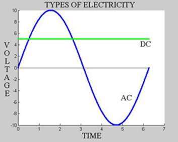
DC and AC (2E1)
 There
are two types of electricity, Direct Current (DC) and Alternating Current
(AC). The graph on the right illustrates these two types.
There
are two types of electricity, Direct Current (DC) and Alternating Current
(AC). The graph on the right illustrates these two types.
Direct Current
(DC)
Direct Current known as DC is a virtually constant voltage that does not change with time, and does not change direction (see green line on graph which shows 5 Volts DC).
Batteries supply Direct Current.
Alternating Current (2E2)
Alternating Current known as AC reverses its direction several/many times per second (see blue line on graph to the right).
Notice how part of the time the Voltage is positive, part of the time the Voltage is negative.
The graph below illustrates how the voltage changes with time.
Dynamos provide alternating current.
Apart from batteries, it is generally easier to generate alternating current than Direct Current.
Type
of AC
|
Frequency
Range
|
|
UK 220 V Mains Supply |
50 Hz |
|
Normal hearing (audio frequencies or af) |
20 Hz to 15 kHz |
|
Range for communications (audio frequencies or af) |
300 Hz to 3 kHz |
|
Radio Frequencies (rf) |
Less than 30 kHz to over 3000 MHz |
Frequency & Wavelength (2E7)
The frequency of an AC signal is measured in Hertz (Hz). One Hertz is one cycle per second.
The wavelength of an AC signal is measure in metres (m).
As you can see from the graph below there is a relationship between Frequency and Wavelength. As the Wavelength reduces, the frequency increases. You can use the graph to convert a wavelength of 6m to a frequency of 50MHz for example.
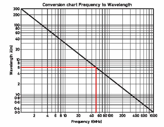
As an alternative to the graph, you can use the formula v = f x λ.
In air the velocity, v of radio waves is a constant (~3x10⁸ m/s).
 So
if the frequency increases, the wavelength decreases, and vice versa.
So
if the frequency increases, the wavelength decreases, and vice versa.
The wavelength of a 50MHz wave 3 x 10⁸ / 50 x 106 = 6m
Analogue & Digital Signals (2F1)
Analogue signals are constantly changing in amplitude (height). They may also change in frequency, or both amplitude and frequency.

Digital signals are a stream of finite values (changing in small steps) measured at a specific sampling interval.

Digital signals can be processed by computing devices with suitable software.
Handling Digital Signals (2F2)
Analogue to Digital Convertors (ADC) are devices used to sample an analogue signal and produce a digital representation of it. A computing device is required to process digital signals.
A Digital to Analogue Convertor (DAC) is a device used to represent a digital signal in an analogue format.
Batteries (2J1)
A battery is a combination of cells usually in series. This enables a higher voltage to be achieved. For example, 8 x 1.5 Volt cells in series will produce 12 Volts.
Batteries provide their electrical energy from stored chemical energy. There is a potential difference across the terminals of a battery.
Non-rechargeable batteries (comprising what is sometimes called primary cells) should not be re-charged and must be properly disposed of.
Rechargeable batteries (comprising what are known as secondary cells) have a reversible chemical process. Be careful with recharging.